1. Axis Control & Spring Modes
With MSFS and X-Plane, TelemFFB is the source of the axis positions the simulator receives. The Axis Control setting (telemffb_controls_axes) enables this: TelemFFB reads your physical stick, applies the spring model and any trim or autopilot offsets, and sends the resulting axis values to the simulator.
MSFS: unbind your axes
MSFS has no toggle to override external axis control. When Axis Control is enabled, you must unbind your joystick and/or pedal axes inside MSFS (or SPAD.neXt). Otherwise MSFS’s own reading of your physical axis will conflict with the position TelemFFB is sending.
X-Plane
You do not need to unbind your axes in X-Plane. The TelemFFB X-Plane plugin uses the simulator’s built-in override datarefs, so the axis is overridden automatically when the feature is enabled.
1.1 Axis Settings
Axis Scale
These sliders scale the axis value sent to the sim. A value of 50% produces 50% control-surface deflection in the sim at 100% physical deflection.
Custom Axis Variables
Some aircraft do not use the standard SimConnect axis events, or use custom L: variables. Use these checkboxes to override the default variable sent, or to enter a custom one. Enter VARNAME for a SimVar or L:VARNAME for an L:Var.
1.2 How the Axis Positions Reach the Sim
1.2.1 MSFS
TelemFFB sends each axis over SimConnect using the sim’s standard axis events. Which events are used depends on the aircraft class:
| Axis | Fixed wing | Helicopter |
|---|---|---|
| X (roll) | AXIS_AILERONS_SET |
AXIS_CYCLIC_LATERAL_SET |
| Y (pitch) | AXIS_ELEVATOR_SET |
AXIS_CYCLIC_LONGITUDINAL_SET |
| Rudder / pedals | AXIS_RUDDER_SET |
ROTOR_AXIS_TAIL_ROTOR_SET |
| Collective | - | AXIS_COLLECTIVE_SET |
The physical axis position is mapped onto the event’s full input range (±16384). Axis curves are not supported in this implementation, but the Axis Scale sliders above can reduce sensitivity - a scale of 50% sends only half the input range across the full physical travel, giving less sensitive control at the expense of range of movement.
The Custom Axis Variables option replaces the standard event for an axis: TelemFFB writes the position to the SimVar or L:Var you specify instead.
1.2.2 X-Plane
TelemFFB streams the axis values to its X-Plane plugin, which engages the simulator’s native control overrides and then writes the positions into the sim’s own control datarefs on every flight loop:
| Device | Override dataref | Position dataref |
|---|---|---|
| Joystick | sim/operation/override/override_joystick_rollsim/operation/override/override_joystick_pitch |
sim/joystick/yoke_roll_ratiosim/joystick/yoke_pitch_ratio |
| Pedals | sim/operation/override/override_joystick_heading |
sim/joystick/yoke_heading_ratio |
| Collective | sim/operation/override/override_prop_pitch |
sim/cockpit2/engine/actuators/prop_ratio_all |
The collective mapping is not a workaround: X-Plane has no dedicated collective dataref, and Laminar’s dataref documentation designates the prop handle ratio as the helicopter collective.
Because these overrides are part of the X-Plane SDK, no unbinding is required - while an override is active the sim ignores its own joystick input for that axis. Unlike MSFS, the targets are fixed: there is no Custom Axis Variables option for X-Plane. If an override is ever left stuck (after a TelemFFB crash, for example), the plugin’s menu in X-Plane (Plugins → TelemFFB → Clear All Overrides) resets them.
1.3 Spring Modes
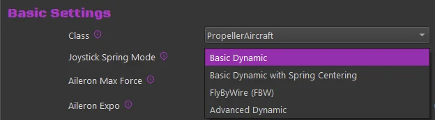
You can configure axis spring gains using one of these modes:
Basic Dynamic — Spring gain changes with dynamic pressure as airspeed changes. Includes additional forces for slip, AoA, and g-loading.
Basic Dynamic with Spring Centering — Adds a fixed centering force to the Dynamic spring effects. The base centering force sets the minimum spring value when airspeed is zero.
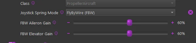
FlyByWire (FBW) — Set a static spring force for each axis.
Advanced Dynamic — Define the spring gain mapping as a visual curve over the aircraft’s speed envelope. See Advanced Spring & G-Force Curves
1.3.1 Dynamic
These settings control the maximum force per axis and the curve for gain application across the aircraft speed envelope.
Max Force Settings
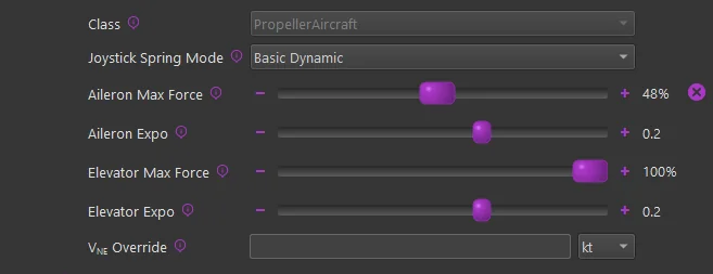
The Max Force settings define the spring gain at VNE (never exceed speed). The calculation uses the aircraft’s known data to determine dynamic pressure (Q) at VNE, then applies that value to the dynamic forces formula. This produces a non-linear gain-to-speed mapping.
The configured Max Force reaches 100% at the aircraft’s VNE speed from telemetry. If the V-speed values in the aircraft configuration are incorrect, use the VNE Override setting to change them.
The Max Force slider handle fades from gray to green as the maximum force approaches. The handle displays the percentage of dynamic force applied.
Expo Settings
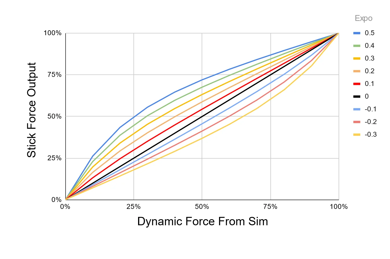
Rhino cannot reproduce real-world control forces. Expo amplifies forces at lower speeds to compensate for reduced stick pressure near stall speed. An Expo value of 0.5 doubles stick forces at 25% of VNE. For jets that need weaker forces until higher speeds, set a negative Expo value.
1.3.2 Dynamic + Spring Centered
Spring Centered uses the same dynamic adjustments described above, with a fixed minimum spring gain for each axis. The dynamic spring gain ranges from the Spring Centered value at low speed to the Max Force value at high speed.

1.3.3 Fly By Wire (FBW)
FBW mode replaces all Dynamic and Spring Centered settings with a fixed gain for each axis. The spring gain does not change with airspeed or aerodynamic conditions.